Your device reaches the app in one line — InstantIoT.begin(...) — and that line says two things: which network the device joins, and where it goes from there. This page lists every combination, explains TLS and the token, walks through the three Bluetooth roads, and ends with what to do when it does not connect.
begin() reads in the order things happen: the device joins a network, then reaches a destination.
InstantIoT.begin(WiFiLink("MyWiFi", "secret"), Cloud(TOKEN));                    // Cloud, TLS
InstantIoT.begin(WiFiLink("MyWiFi", "secret"), MyServer("192.168.1.42", TOKEN)); // your own InstantIoT Server, at home
InstantIoT.begin(EthernetLink(), Cloud(TOKEN));          // a W5100 / W5500 shield

InstantIoT.begin(AccessPoint("MyESP32", "12345678"));   // Direct: the device IS the Wi-Fi network
InstantIoT.begin(BLELink("MyESP32"));                    // Direct: Bluetooth LE — ESP32 family
InstantIoT.begin(BluetoothLink("MyESP32"));              // Direct: Bluetooth Classic — the original ESP32
InstantIoT.begin(SerialLink(Serial1));                   // Direct: a Bluetooth module on a hardware UART
InstantIoT.begin(SerialLink(10, 11));                    // Direct: the same module on two software pins — UNO, Nano, ESP8266
The Direct forms have no destination to name — the phone is at the other end. A pairing the device cannot do fails to compile, and the error says what to write instead. Supported boards says which lines each board takes.
The token
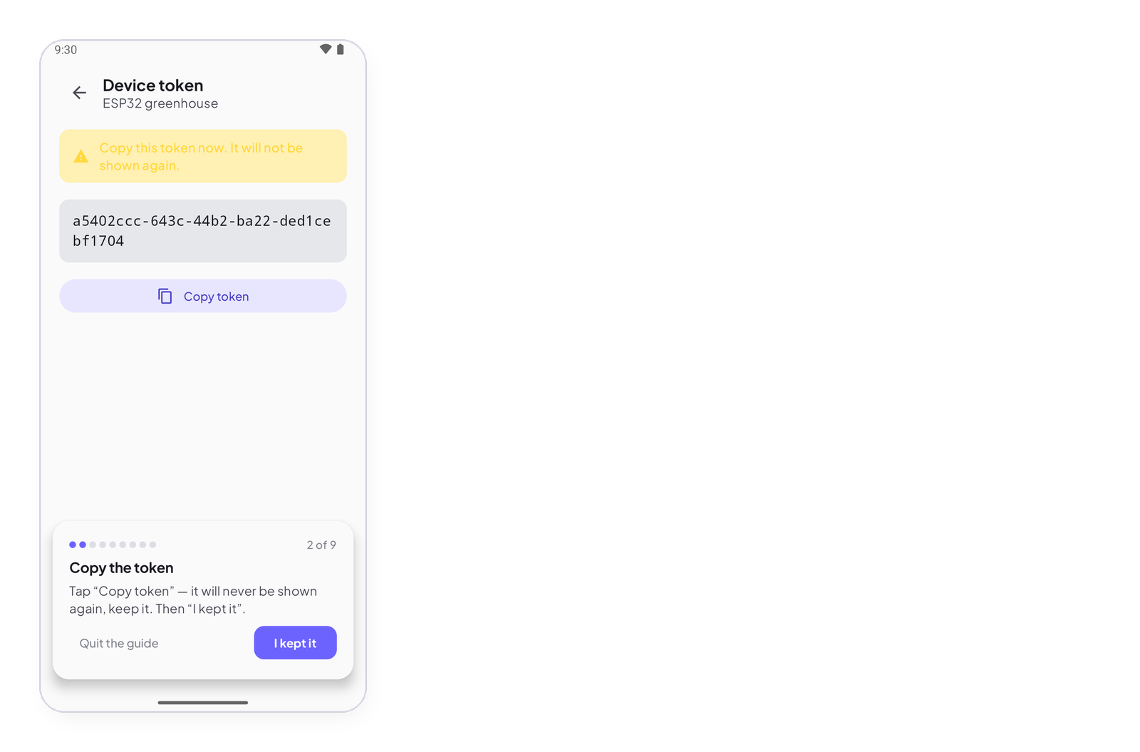
TOKEN is the device’s identity on the Cloud. You get it once, when you register the device in the app (device icon → Register a board → Copy token). Keep it in the sketch; never share it. Lost it? Register the device again.
#include <InstantIoT.h>

const char* WIFI_SSID    = "MyWiFi";
const char* WIFI_PASS    = "secret";
const char* DEVICE_TOKEN = "paste-the-token-the-app-gave-you";
InstantTimer timers;

void publish() { InstantIoT.write(I0, analogRead(A0) * 3.3 / 4095.0); }

void setup() {
    Serial.begin(115200);
    if (!InstantIoT.begin(WiFiLink(WIFI_SSID, WIFI_PASS), Cloud(DEVICE_TOKEN))) {
        Serial.println("Not connected yet — the device keeps trying.");   // normal on the first pass
    }
    timers.every(2000, publish);
}

void loop() { InstantIoT.loop(); timers.run(); }
begin() returns false when the network or the server is not there yet; loop() keeps trying, with a growing delay, and the device token is what makes the server accept it. A connection the server accepts and drops within seconds is a wrong token.
Your own server
Same sketch, another far end: MyServer(host, TOKEN) reaches an InstantIoT Server on your network, on its TCP port (9001 by default). Plaintext, because a server at your place does not leave your place; .secure() in front of a server with TLS.
#include <InstantIoT.h>

const char* WIFI_SSID    = "MyWiFi";
const char* WIFI_PASS    = "secret";
const char* SERVER_HOST  = "192.168.1.42";                  // or raspberrypi.local
const char* DEVICE_TOKEN = "the-token-your-server-gave-you";
InstantTimer timers;

void publish() { InstantIoT.write(I0, analogRead(A0) * 3.3 / 4095.0); }

void setup() {
    Serial.begin(115200);
    InstantIoT.begin(WiFiLink(WIFI_SSID, WIFI_PASS), MyServer(SERVER_HOST, DEVICE_TOKEN));
    // InstantIoT.begin(WiFiLink(WIFI_SSID, WIFI_PASS), MyServer(SERVER_HOST, 9443, DEVICE_TOKEN).secure());   // behind a TLS front, on its port
    timers.every(2000, publish);
}

void loop() { InstantIoT.loop(); timers.run(); }
Ethernet
A W5100 / W5500 shield or module instead of the radio: EthernetLink(), and the destination does not change. Ethernet is opt-in — #define INSTANTIOT_ETHERNET 1 before the include, because the Arduino build only finds a library it sees included. On an ESP32 the module is driven behind the chip’s own network stack, so TLS works and the three wiring pins are named; everywhere else the cable goes through the TCP stack inside the W5500, which carries no TLS — Cloud(TOKEN).plaintext(), and the token travels readable on your network.
// A Mega, an UNO, an R4 with an Ethernet shield — plaintext, no SSID, no password
#define INSTANTIOT_ETHERNET 1
#include <InstantIoT.h>

const char* DEVICE_TOKEN = "paste-the-token-the-app-gave-you";
InstantTimer timers;

void publish() { InstantIoT.write(I0, analogRead(A0) * 5.0 / 1023.0); }

void setup() {
    Serial.begin(115200);
    InstantIoT.begin(EthernetLink(), Cloud(DEVICE_TOKEN).plaintext());   // false on the first pass while DHCP answers
    timers.every(2000, publish);
}

void loop() { InstantIoT.loop(); timers.run(); }
// An ESP32 with a W5500 module — TLS, and the pins you wired
#define INSTANTIOT_ETHERNET 1
#include <InstantIoT.h>

const char* DEVICE_TOKEN = "paste-the-token-the-app-gave-you";
#define W5500_CS   5
#define W5500_IRQ  4
#define W5500_RST 14

void setup() {
    InstantIoT.begin(EthernetLink(W5500_CS, W5500_IRQ, W5500_RST), Cloud(DEVICE_TOKEN));
}

void loop() { InstantIoT.loop(); }
Loop
Call InstantIoT.loop() on every pass of loop(), and never delay() — it stops reading incoming frames and sending the heartbeat, and the server marks the device offline. For timing, use the timer that comes with the header:
#include <InstantIoT.h>

const char* TOKEN = "paste-the-token-the-app-gave-you";
InstantTimer timers;

void publish() { InstantIoT.write(I0, readSensor()); }      // once a second
void blink()   { digitalWrite(LED_BUILTIN, !digitalRead(LED_BUILTIN)); }

void setup() {
    pinMode(LED_BUILTIN, OUTPUT);
    InstantIoT.begin(WiFiLink("MyWiFi", "secret"), Cloud(TOKEN));
    timers.every(1000, publish);
    timers.every(250, blink);
}

void loop() {
    InstantIoT.loop();          // reads what the app wrote, sends the heartbeat, reconnects if needed
    timers.run();               // fires what is due — no delay() anywhere
}
InstantIoT.connected() says whether the far end is there; write() returns false while it is not. The heartbeat goes every 5 s by default — Cloud(TOKEN).heartbeatEvery(20000) to change it, between 1 s and 48 s.
TLS, and how to step out of it
Cloud(TOKEN) encrypts and verifies the server’s identity. Three ways out, and they do not mean the same thing:
Cloud(TOKEN).withCertificate(MY_ROOT)  // your own authority — still verified
Cloud(TOKEN).withoutCertCheck()        // encrypted, identity unchecked — bring-up only
Cloud(TOKEN).plaintext()               // no encryption at all — the token travels readable
plaintext() links no TLS stack at all — 93 KB the device never has to carry. It is a decision, never a default.
#include <InstantIoT.h>

const char* TOKEN = "paste-the-token-the-app-gave-you";

// Your own authority — the root of the certificate your server presents, PEM
const char* MY_ROOT = R"(-----BEGIN CERTIFICATE-----
MIIB...your root...
-----END CERTIFICATE-----
)";

void setup() {
    InstantIoT.begin(WiFiLink("MyWiFi", "secret"), Cloud(TOKEN).withCertificate(MY_ROOT));
    // bring-up, on a bench: Cloud(TOKEN).withoutCertCheck()
    // a board with no TLS stack, an Ethernet shield on a Mega: Cloud(TOKEN).plaintext()
}

void loop() { InstantIoT.loop(); }
On the MKR WiFi 1010, the Nano 33 IoT and the UNO WiFi Rev2 the roots live in the Wi-Fi module’s firmware and withCertificate() is ignored — the library says so; update the firmware with the IDE’s WiFiNINA Firmware Updater, or plaintext().
Direct over Wi-Fi: the device is the network
AccessPoint(name, password) makes the device open its own Wi-Fi network; the phone joins it and talks to the device. Eight characters or more for the password, or nothing starts. ESP32 family, ESP8266, UNO R4 WiFi, MKR WiFi 1010, Nano 33 IoT, UNO WiFi Rev2. While the phone is on that network it has no Internet, and Android or iOS may drop it after a while — reopen the connection from the device icon.
#include <InstantIoT.h>

const char* AP_SSID     = "MyESP32";      // the network the device opens — what the phone will see
const char* AP_PASSWORD = "12345678";     // 8 characters or more
InstantTimer timers;

ISimpleButton(I0) {                       // a button in the app
    WHEN_PRESSED  { digitalWrite(LED_BUILTIN, HIGH); }
    WHEN_RELEASED { digitalWrite(LED_BUILTIN, LOW);  }
};

void publish() { InstantIoT.write(I1, analogRead(A0) * 3.3 / 4095.0); }

void setup() {
    Serial.begin(115200);
    pinMode(LED_BUILTIN, OUTPUT);
    InstantIoT.begin(AccessPoint(AP_SSID, AP_PASSWORD));   // no token, no destination: the phone is the far end
    timers.every(2000, publish);
}

void loop() { InstantIoT.loop(); timers.run(); }
In the app: device icon → Settings → Open the connection, pick MyESP32 in the list. The device listens on 192.168.4.1, port 8080; the app knows.
Direct over Bluetooth: three roads
Bluetooth is the other way to stay next to the device, and the library compiles three forms of it. The bytes on the wire are the same as over Wi-Fi: a signal does not know how it travelled, and the rest of the sketch — the blocks, write(), the timer — never changes.
| Device | Phone | begin() line |
|
|---|---|---|---|
| Bluetooth LE, native | ESP32, -S3, -C3, -C6 | Android, iOS | BLELink("MyESP32") |
| Bluetooth Classic, native | the original ESP32 only | Android only | BluetoothLink("MyESP32") |
| A Bluetooth module on two wires — HC-05 / HC-06 (Classic), HM-10 (LE) | any board with a spare UART or two free pins | Android; iOS with an HM-10 | SerialLink(Serial1) or SerialLink(rx, tx) |
Verified end to end on the bench, September 2026 — button, slider, chart, both ways: UNO R4 WiFi + BLE module, ESP8266 + BLE module, ESP32 native BLE, ESP32 Classic.
Bluetooth LE on the ESP32 — BLELink
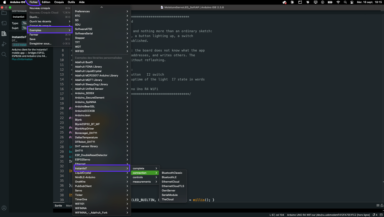
The device advertises under the name you give; the app scans, finds it and connects. Nothing to pair in the phone’s settings. It needs the NimBLE-Arduino library (Library Manager → search NimBLE-Arduino → Install), and the sketch must include it before InstantIoT.h — not as decoration: without that line, BLELink does not exist at all, because the Arduino build only finds a library it sees included.
#include <NimBLEDevice.h>     // BEFORE InstantIoT.h, always
#include <InstantIoT.h>

const char* BOARD_NAME = "MyESP32";       // the name the app shows while scanning
InstantTimer timers;

ISimpleButton(I0) {
    WHEN_PRESSED  { digitalWrite(LED_BUILTIN, HIGH); }
    WHEN_RELEASED { digitalWrite(LED_BUILTIN, LOW);  }
};

void publish() { InstantIoT.write(I1, temperatureRead()); }   // the ESP32's own sensor, for the bench

void setup() {
    Serial.begin(115200);
    pinMode(LED_BUILTIN, OUTPUT);
    if (InstantIoT.begin(BLELink(BOARD_NAME))) Serial.println("BLE advertising");
    else                                        Serial.println("BLE failed to start");
    timers.every(2000, publish);
}

void loop() { InstantIoT.loop(); timers.run(); }
If the build stops on text section exceeds available space in board, the Bluetooth stack does not fit in the default 1.3 MB application partition: Tools → Partition Scheme → Huge APP (3 MB No OTA / 1 MB SPIFFS). The menu only appears for a board that has it — with a generic module, pick ESP32 Dev Module in Tools → Board.
Bluetooth Classic on the original ESP32 — BluetoothLink
Serial Port Profile, the way a speaker or an old GPS connects. Only the original ESP32 has the radio: the S3, C3 and C6 have BLE only, the S2 has no Bluetooth at all, and on those four BluetoothLink does not compile — the message says so. And Android only: iOS does not open Bluetooth Classic to apps, so the app does not offer it on an iPhone.
#include <InstantIoT.h>

const char* BOARD_NAME = "MyESP32";       // the name in the phone's pairing list
InstantTimer timers;

ISimpleButton(I0) {
    WHEN_PRESSED  { digitalWrite(LED_BUILTIN, HIGH); }
    WHEN_RELEASED { digitalWrite(LED_BUILTIN, LOW);  }
};

void publish() { InstantIoT.write(I1, temperatureRead()); }

void setup() {
    Serial.begin(115200);
    pinMode(LED_BUILTIN, OUTPUT);
    if (InstantIoT.begin(BluetoothLink(BOARD_NAME))) Serial.println("Bluetooth ready — pair with MyESP32");
    else                                              Serial.println("Bluetooth failed to start");
    timers.every(2000, publish);
}

void loop() { InstantIoT.loop(); timers.run(); }
Two things before the app sees the device. The partition scheme is not optional here: Bluetooth Classic plus Wi-Fi is 122 % of the default partition, so Tools → Partition Scheme → Huge APP every time. And pair first, in Android’s Bluetooth settings — the device appears under its name, no PIN — then open the project in the app and connect.
A Bluetooth module on two wires — SerialLink
For a board with no radio of its own — an UNO, a Nano, a Mega — or for any board when you would rather not touch its radio: an HC-05 or HC-06 (Bluetooth Classic) or an HM-10 (Bluetooth LE) does the talking, and SerialLink hands it the bytes. The phone connects to the module; the board never knows there is Bluetooth.
SerialLink exists in two forms, and the board decides which one:
InstantIoT.begin(SerialLink(Serial1));    // a hardware UART — UNO R4 WiFi, MKR WiFi 1010, Nano 33 IoT,
                                          // UNO WiFi Rev2, Mega 2560, ESP32 family
InstantIoT.begin(SerialLink(10, 11));     // two software pins (RX, TX) — UNO, Nano
InstantIoT.begin(SerialLink(13, 15));     // the same on an ESP8266 — D7, D8
SerialLink(Serial1)— the UART the chip already has. No bit-banging, no speed ceiling; prefer it wherever it exists.Serial1is on pins D0 / D1 of the UNO R4 WiFi, the Nano 33 IoT and the UNO WiFi Rev2, on 13 / 14 of the MKR WiFi 1010, on 19 / 18 (RX1 / TX1) of the Mega; on the ESP32 family its pins depend on the board, check its pinout.SerialLink(rx, tx)— two ordinary pins driven by SoftwareSerial, which exists in the AVR core and the ESP8266 one and nowhere else. 10 / 11 on an UNO or a Nano — the most common wiring, not a rule, but the RX pin must be interrupt-capable and 10 is. 13 / 15 on an ESP8266 (D7 / D8), because GPIO 9 to 11 talk to the flash there. A board without SoftwareSerial refuses this form with one sentence — SoftwareSerial does not exist on this board … write SerialLink(Serial1) instead — rather than a page of templates.
The speed is 9600 baud by default, what these modules ship at; SerialLink(Serial1, 38400) changes it. SoftwareSerial is reliable up to about 57 600.
Wiring. Four wires. The module listens on its RX and talks on its TX, so the two cross:
| Module pin | Goes to | On a 5 V board (R4, UNO, Mega) | On a 3.3 V board (ESP8266, ESP32) |
|---|---|---|---|
| TX | the board’s RX — RX1, D0, or your rx pin |
direct wire | direct wire |
| RX | the board’s TX — TX1, D1, or your tx pin |
through a divider: 1 kΩ from the board’s TX, 2 kΩ to GND, the module’s RX on the middle — 5 V becomes 3.3 V | direct wire |
| VCC | 5 V | the breakout has its own regulator | 5 V (VIN) |
| GND | GND |
An HC-05 or HC-06 has to be paired in Android’s Bluetooth settings first — PIN 1234, or 0000 — before the app lists it. An HM-10 needs no pairing: the app scans and connects, on Android and on iOS.
One sketch for every board — the two #if lines pick the road, the rest never changes:
#include <InstantIoT.h>

#if defined(ESP8266)
  #define RX_PIN 13                       // D7 — module TX
  #define TX_PIN 15                       // D8 — module RX
#elif defined(ARDUINO_ARCH_AVR) && !defined(HAVE_HWSERIAL1)
  #define RX_PIN 10                       // UNO, Nano — module TX
  #define TX_PIN 11                       //             module RX, through the divider
#endif

InstantTimer timers;

ISimpleButton(I0) {
    WHEN_PRESSED  { digitalWrite(LED_BUILTIN, HIGH); }
    WHEN_RELEASED { digitalWrite(LED_BUILTIN, LOW);  }
};

void publish() { InstantIoT.write(I1, analogRead(A0)); }

void setup() {
    Serial.begin(9600);                   // the USB monitor; the module has its own line
    pinMode(LED_BUILTIN, OUTPUT);
#if defined(RX_PIN)
    InstantIoT.begin(SerialLink(RX_PIN, TX_PIN));       // two software pins
#else
    InstantIoT.begin(SerialLink(Serial1));              // the hardware UART — R4, MKR, Nano 33 IoT, Rev2, Mega, ESP32
#endif
    timers.every(5000, publish);          // five seconds, not two: at 9600 baud the line is narrow
}

void loop() { InstantIoT.loop(); timers.run(); }
Choosing the board and the connection in the app
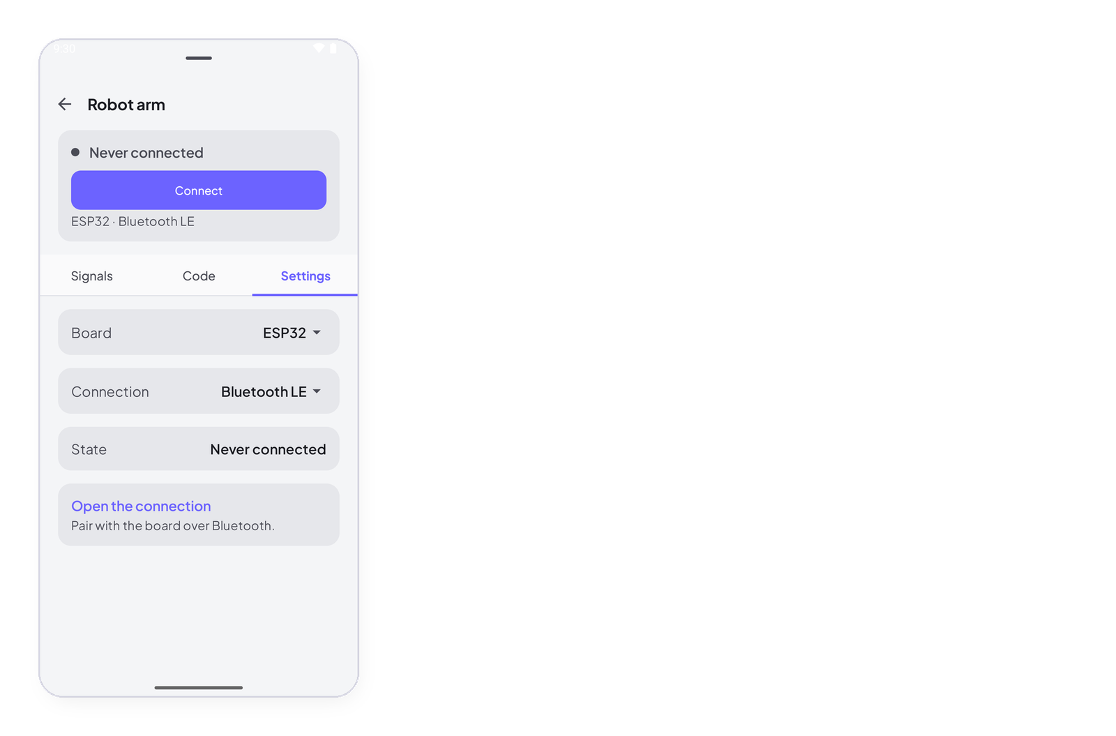
You pick both when you create a Direct project: the board in the list, the connection among the chips the board can do — Wi-Fi, Bluetooth LE, Bluetooth Classic, Bluetooth module. The app writes the matching begin() line, the #include that goes with it, and the wiring in a comment.
Both change later on the device sheet, Settings tab → Board / Connection. Changing them touches one line of the sketch — begin() — and nothing else: the widgets, the signals and the blocks stay. The four connections, as the Code tab writes them for an ESP32:
// Wi-Fi
const char* AP_SSID     = "MyESP32";
const char* AP_PASSWORD = "12345678";
InstantIoT.begin(AccessPoint(AP_SSID, AP_PASSWORD));

// Bluetooth LE — with #include <NimBLEDevice.h> added above <InstantIoT.h>
const char* BOARD_NAME = "MyESP32";
InstantIoT.begin(BLELink(BOARD_NAME));

// Bluetooth Classic
const char* BOARD_NAME = "MyESP32";
InstantIoT.begin(BluetoothLink(BOARD_NAME));

// Bluetooth module — SerialLink(Serial1) on this board; RX_PIN / TX_PIN on an UNO, a Nano, an ESP8266
InstantIoT.begin(SerialLink(Serial1));
When it does not connect
- The dot stays grey. Wi-Fi name or password: the device says so on the Serial monitor at 115200.
- Connected, then dropped after a minute. The sketch has a
delay()or a blocking loop: the heartbeat could not go out. UseInstantTimer. - Connected, but a value never shows. The address is not declared in the app, or its type does not match (
floatsent to anintsignal). The server drops it without a word — check your device → signals. - A widget does nothing, and everything else works. The widget is on the wrong signal: a button wired to
I1while the sketch’s block readsI0. Open the widget, Data tab, and check the address against the block —I0,I1,I2are three different wires. error: 'IO' was not declared— capital O instead of zero inI0.'BLELink' was not declared—#include <NimBLEDevice.h>is missing, or comes after<InstantIoT.h>. NimBLE-Arduino installed, the include first.text section exceeds available space in board, or the ESP32 sketch does not fit — Tools → Partition Scheme → Huge APP. Bluetooth Classic never fits in the default partition; BLE sometimes does not.SoftwareSerial does not exist on this board— the R4, the MKRs, the ESP32 have no software serial. Move the module toSerial1and writeSerialLink(Serial1).- The ESP32 restarts in a loop, Brownout detector was triggered on the Serial monitor. The radio draws a burst the USB link cannot give: a thin cable, a hub, a weak port. Change the cable, plug straight into the computer, and if it persists put a 100 to 470 µF capacitor between 5 V (or 3V3) and GND, close to the module.
- The HC-05 never appears in the app. It has to be paired in Android’s Bluetooth settings first —
1234or0000; until then the app does not see it. An HM-10 (LE) is found by scanning and needs no pairing. - Values arrive garbled or not at all over a module. The speeds do not match — the module’s default is 9600,
SerialLink(...)is 9600 unless you said otherwise — or the sketch sends too fast. SoftwareSerial tops out around 57 600 baud, and at 9600 a frame that is still going out when the next one starts is a frame nobody reads: leave one to two seconds between two writes on the same signal (timers.every(2000, ...)). - The app connects to the module, the board never reacts. TX and RX are swapped (the module’s TX goes to the board’s RX), or a 5 V board is driving the module’s RX without a divider.