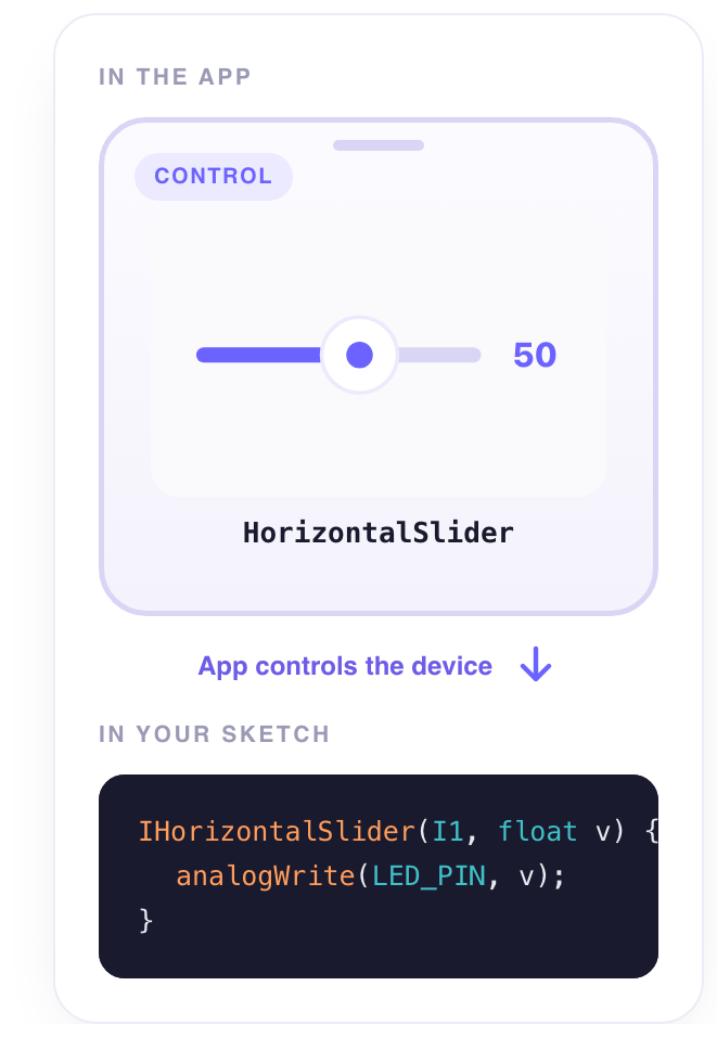
A value between two bounds, set by dragging the thumb. Brightness, speed, a temperature setpoint — anything that is not on or off but how much.
What it does
As the thumb moves, the slider writes the value to its signal. The range is the signal’s own: the minimum and maximum you set in the signal’s format (device → signal → Format) are the two ends of the track, so a slider on a 0 – 255 signal writes 0 – 255, and one on a 5 – 30 °C setpoint writes degrees. With a step, the thumb snaps to multiples — 0, 5, 10… — instead of every value in between.
When to use it
- A dimmer or a fan — a PWM output from 0 to 255.
- A setpoint — the temperature a thermostat aims for. This is a state: see
ISignalbelow. - A servo angle —
0 – 180, with a step of5for a steady hand.
Set it up
- Give the signal its range — A slider goes from the signal’s minimum to its maximum, so set them first: tap the device icon, open the signal, and fill in Minimum and Maximum under Format —
0and255for a PWM, say. - Place it — Back on the dashboard, tap + and choose Horizontal Slider under Controllers. Twelve columns wide reads best.
- Wire it to the signal — Tap the slider, open the Data tab, tap + Add a target and pick that signal.
- Try it — Close the settings, tap ▶, and drag the thumb: the device receives the value as you move.
Settings
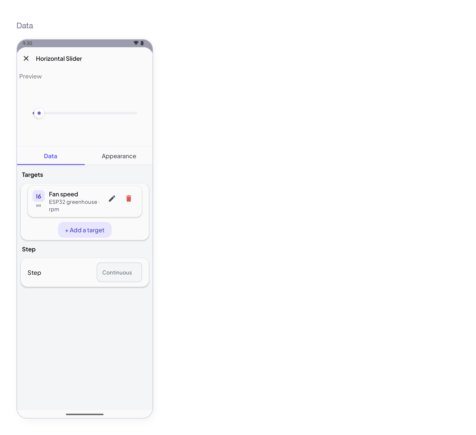
Tap the widget in edit mode: the sheet opens with a live preview at the top, then two tabs — Data for what it reads or writes, Appearance for how it looks.
Data — what it writes
Targets
| Setting | Type | Default | What it controls |
|---|---|---|---|
| Targets | list of signals | empty — No target yet. The tap goes nowhere. | The signal the widget writes to. Accepts an Integer or Decimal signal — Decimal for a setpoint with fractions (22.5), Integer for a PWM (0 – 255). Minimum and maximum are the signal’s: set them once in the signal’s format. The picker lists nothing else. + Add a target for a second device: every target gets the value. |
Step
| Setting | Type | Default | What it controls |
|---|---|---|---|
| Step | Continuous / a number | Continuous | Continuous: every value along the track. A number: the thumb snaps to multiples of it. |
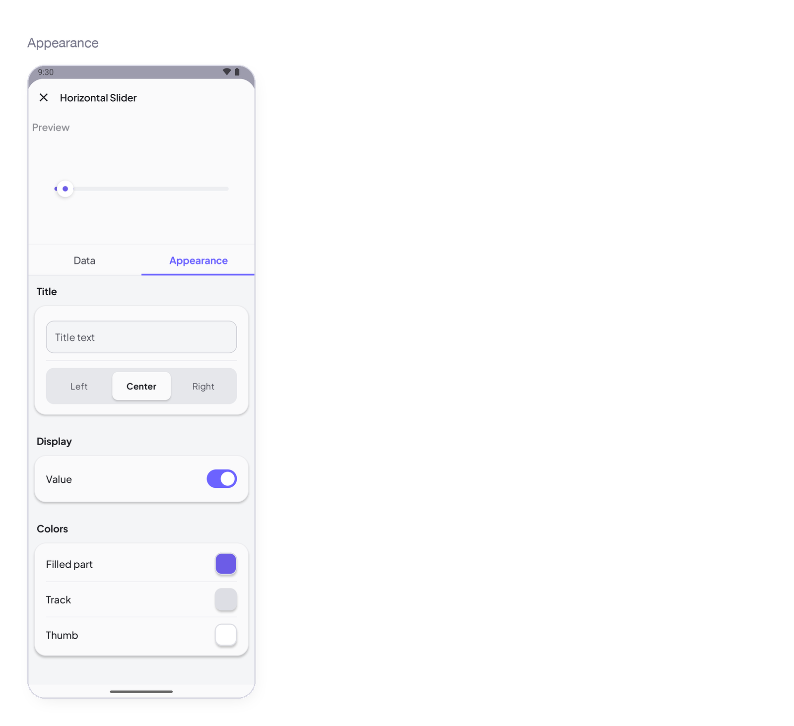
Appearance — how it looks
Title
| Setting | Type | Default | What it controls |
|---|---|---|---|
| Title text | text | empty | A title above the widget. Empty means no title. |
| Alignment | Left / Center / Right | Center | Where the title sits. |
Display
| Setting | Type | Default | What it controls |
|---|---|---|---|
| Value | toggle | on | Show the current value next to the thumb, with the signal’s unit. |
Colors
| Setting | Type | Default | What it controls |
|---|---|---|---|
| Filled part | colour | theme accent | The track from the start to the thumb. |
| Track | colour | theme | The rest of the track. |
| Thumb | colour | white | The knob. |
States
- Dragging — the value is written as the thumb moves, paced so the device gets a stream, not a flood.
- Released — the last value stays; the slider shows it.
- Device offline — the last position waits in the Cloud; with
ISignaland Restore, the device gets it on reconnect.
Arduino device code
The address is all the device knows — I1 here; use the one the app gave your signal. In the sketch, the block receives the value:
IHorizontalSlider(I1, float v) { … };
Complete sketch — Cloud
Paste it into the Arduino IDE, put your Wi-Fi and the token the app gave you, upload.
#include <InstantIoT.h>

const char* WIFI_SSID    = "MyWiFi";
const char* WIFI_PASS    = "MyPassword";
const char* DEVICE_TOKEN = "PASTE_TOKEN_HERE";

const int PWM = 5;

IHorizontalSlider(I1, float v) {       // the signal is 0 – 255 in the app
    analogWrite(PWM, (int) v);
};

void setup() {
    Serial.begin(115200);
    pinMode(PWM, OUTPUT);
    InstantIoT.begin(WiFiLink(WIFI_SSID, WIFI_PASS), Cloud(DEVICE_TOKEN));
}

void loop() {
    InstantIoT.loop();
}
Other connections
The widget block never changes. Only the begin() line says how the device reaches the app:
| Connection | begin() |
Devices |
|---|---|---|
| Cloud over Wi-Fi (above) | InstantIoT.begin(WiFiLink("MyWiFi", "secret"), Cloud(DEVICE_TOKEN)); |
ESP32 family, ESP8266, UNO R4 WiFi, MKR WiFi 1010, Nano 33 IoT, UNO WiFi Rev2 |
| Cloud over Ethernet | InstantIoT.begin(EthernetLink(), Cloud(DEVICE_TOKEN)); |
any board + an Ethernet shield |
| Direct — the device’s own Wi-Fi | InstantIoT.begin(AccessPoint("MyESP32", "12345678")); |
every board with Wi-Fi |
| Direct — Bluetooth LE | InstantIoT.begin(BLELink("MyESP32")); — #include <NimBLEDevice.h> first |
ESP32 family (not the S2) |
| Direct — Bluetooth Classic | InstantIoT.begin(BluetoothLink("MyESP32")); |
the original ESP32, Android only |
| Direct — a Bluetooth module (HC-05, HM-10) | InstantIoT.begin(SerialLink(Serial1)); — or SerialLink(13, 15) on ESP8266, SerialLink(10, 11) on UNO / Nano |
every board, radio or not |
| Your own InstantIoT Server (open source, at home) | InstantIoT.begin(WiFiLink("MyWiFi", "secret"), MyServer("192.168.1.42", DEVICE_TOKEN)); |
same as Cloud |
Direct needs no token: the phone is at the other end of the wire. See Connect for TLS, timeouts and what to do when it does not connect.
ISignaldoes the same job — and survives a restart.ISignal(I1, float v)runs with exactly the same value asIHorizontalSlider(I1, float v): the widget block is the readable form,ISignalthe generic one, and you can use either. The difference shows when the device reconnects: with Restore after a restart on the signal, the Cloud sends the last value again and only theISignalblock runs — a slider position is a state. WriteISignal(I1, float v)and turn Restore on, and the dimmer comes back at yesterday’s level by itself, phone off. See One block for everything.
Notes
- Declare the signal as Decimal if you want fractions (
22.5 °C), Integer for a PWM. - Keep the block short: set the output and return. The device receives many values while you drag.
- For a value the device must keep across restarts, the block to write is
ISignal— see above.
Next
→ Vertical Slider — the same, upright → Joystick — two values in one gesture